
- 非IC关键词
西安尚平电子科技有限公司

- 营业执照:未审核经营模式:其他所在地区:陕西 西安
收藏本公司 人气:37277
企业档案
- 相关证件:
- 会员类型:普通会员
- 马女士

- 电话:029-81777783
- 手机:18092826768
- 地址:长安南路449号
- 传真:029-87878338
- E-mail:xacomponents@163.com
您的当前位置:西安尚平电子科技有限公司 > 元器件产品
产品信息
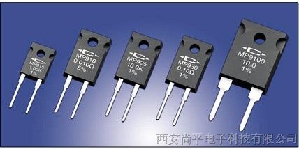
Power Film Resistors TO-126, TO-220 and TO-247 Style
15 Watts at +25°C Case Temperature, derated to zero at +150°C.
Exposed Ceramic Heat Dissipating Mounting Surface.
Resistance Range of 0.020 ohm to 1 K.
Non-Inductive Design.
Use your thermal design experience with power semiconductors in TO-126, TO-220,
and TO-247 style power packages to help you get the most out of this unique family of
power resistors. The thermal design issues are the same where power handling
capability is based on the case temperature which is maintained in your design.
MP915 TO-126 Style Power Package
Up to 30 Watts at +25°C Case Temperature, derated to zero at +150°C.
Exposed Ceramic Heat Dissipating Mounting Surface.
Resistance Range of 0.010 ohm to 100 K.
Non-Inductive Design.
MP916, MP925, and MP930 TO-220 Style Power Package
100 Watts at +25°C Case Temperature, derated to zero at +175°C.
Exposed Ceramic Heat Dissipating Mounting Surface.
Resistance Range of 0.050 ohm to 100 ohm.
Non-Inductive Design.
MP9100 TO-247 Style Power Package
Low Cost Heat Sink Mountable Design featuring
an Exposed Ceramic Heat Dissipating Mounting Surface
The MP900 and MP9000 Series Kool-Pak®
Power
Film Resistors are constructed with Caddock's
Micronox®
resistance film fired onto a flat ceramic
substrate. The terminal attachment and resistance
element geometry are configured to provide
outstanding non-inductive performance. The
ceramic substrate is positioned in the molded
package such that the resistor element and terminal
attachment areas on the substrate are
encapsulated in the molded body with the other side
of the ceramic being exposed flush with the back
mounting surface of the device. This construction is
covered by one or more issued patents, also
patents pending.
For custom resistance values and tolerances contact
applications engineering.
Construction of MP900 and
MP9000 Series:
0.020 Ω 5%
0.025 Ω 5%
0.030 Ω 5%
0.033 Ω 5%
0.040 Ω 5%
0.050 Ω
0.075 Ω
0.10 Ω
0.15 Ω
0.20 Ω
0.25 Ω
0.30 Ω
0.33 Ω
0.40 Ω
0.50 Ω
0.75 Ω
1.00 Ω
1.50 Ω
2.00 Ω
2.50 Ω
3.00 Ω
3.30 Ω
4.00 Ω
5.00 Ω
7.50 Ω
8.00 Ω
10.0 Ω
12.0 Ω
15.0 Ω
20.0 Ω
25.0 Ω
27.0 Ω
30.0 Ω
33.0 Ω
40.0 Ω
47.0 Ω
50.0 Ω
56.0 Ω
75.0 Ω
100 Ω
120 Ω
150 Ω
200 Ω
250 Ω
300 Ω
330 Ω
400 Ω
470 Ω
500 Ω
560 Ω
750 Ω
1.00 K
1.50 K
2.00 K
2.50 K
3.00 K
3.30 K
4.00 K
5.00 K
7.50 K
MP915, MP925, and MP930
Standard Resistance Values:
Tolerance MP915, MP925, and MP930 ±1% Standard - except
as noted. (5% and 20% are available for most resistance values).
0.050 Ω
0.075 Ω
0.10 Ω
0.15 Ω
0.20 Ω
0.25 Ω
0.30 Ω
0.33 Ω
0.40 Ω
0.50 Ω
0.75 Ω
1.00 Ω
1.50 Ω
2.00 Ω
2.50 Ω
3.00 Ω
3.30 Ω
4.00 Ω
5.00 Ω
7.50 Ω
8.00 Ω
10.0 Ω
12.0 Ω
15.0 Ω
MP9100 Standard Resistance Values:
Tolerance MP9100 ±1% Standard.
20.0 Ω
25.0 Ω
27.0 Ω
30.0 Ω
33.0 Ω
40.0 Ω
47.0 Ω
50.0 Ω
56.0 Ω
75.0 Ω
100 Ω
Ordering Information:
MP915 - 50.0 - 1%
Model Number:
Resistor Value:
Tolerance
10.0 K
15.0 K
20.0 K
25.0 K
30.0 K
33.0 K
40.0 K
47.0 K
50.0 K
56.0 K
68.0 K
75.0 K
82.0 K
100 K
0.010 Ω 5%
0.015 Ω 5%
MP916 Standard Resistance Values:
Tolerance MP916 ±5% Standard (20% is available).
Packaging: MP915, MP916, MP925, MP930
resistors are packaged in plastic shipping tubes,
50 pieces per tube. These resistors are available
in a 50 piece minimum quantity and in full tube
quantity increments (i.e. 50, 100, 150, etc.). The
MP9100 resistors are packaged in plastic shipping
tubes, 25 pieces per tube.NewPower Resistor with Exposed Ceramic Heat DissipatingMounting Surface.
100 175
0
20
40
100
POWER RATING, %
80
60
150
A
B
25
A - MP915, MP916, MP925, MP930 Max. Temperature, TMax = 150°C
B - MP9100 Max. Temperature, TMax = 175°C
CASE TEMPERATURE, °C
DIMENSIONS IN INCHES AND (MILLIMETERS)
Figure 3
TO-247 Style
MP9100
All power and associated overload ratings are derated
based upon case temperature using the derating curve.
The case temperature is measured at the center of the
ceramic mounting surface, with the part properly
mounted and under electrical load. Without a heat sink,
when in free air at +25°C, the MP915 is rated for 1.25
watts, the MP916, MP925, MP930 are rated for 2.25
watts, and the MP9100 is rated for 3.5 watts.
The thermal design should satisfy the following equation:
Case Temperature (T
c
) + [Thermal Resistance (RθJC) x power applied (Watts)] ≤ TMAX
considering the full
operating temperature range of the application.
Mounting Note: Mount on a smooth, clean, and flat heat sink surface with a thermal interface material, such
as thermal grease. The entire exposed ceramic portion must be in thermal contact with the heat sink. When
screw mounting, use a compression washer which provides a mounting force of 150 to 300 pounds (665 to
1330 N). This will provide sufficient pressure on the package over time and through large temperature variations to maintain the maximum power dissipation capability. Mounting torque to avoid package damage is 8
in-lbs. (0.90 N-m). If a spring clip is used, a clip force of 8 to 30 pounds (35 to 130 N) is recommended to be
applied to the center of the package. The clip should be round or smooth in the contact area to avoid concentrating the load on a small point of the plastic body of the package. Another mounting option is to use a
pressure bar method which can achieve a greater mounting force with a greater contact area.
For additional applications information regarding mounting and pulse handling see the Caddock
Applications Notes at caddock.com or contact Applications Engineering.
Derating Curve Specifications:
Temperature Coefficient for MP915, MP916,
MP925, and MP930:
TC referenced to +25°C, ΔR taken at +150°C
0.50 ohms and above, -20 to +80 ppm/°C
0.050 ohm to 0.49 ohms, 0 to +200 ppm/°C
0.020 ohm to 0.049 ohm, 0 to +300 ppm/°C
0.010 ohm to 0.019 ohm, 0 to +500 ppm/°C
Temperature Coefficient for MP9100:
TC referenced to +25°C, ΔR taken at +175°C
0.50 ohms and above, -20 to +80 ppm/°C
0.050 ohm to 0.49 ohms, 0 to +150 ppm/°C
Operating Temperature: -55°C to TMAX
Inductance: MP915, MP916, MP925, and MP930
10nH typical; MP9100, 20nH typical, in series when
measured at a point 0.2 inches from the resistor
body.
DWV: The dielectric strength rating of 1500 VrmsAC
is based upon connections made between
terminals shorted, and the metal surface the part is
mounted to or a metal clip in contact with the top
surface of the part.
Insulation Resistance: 10,000 Megohms min.
The resistor element is electrically isolated from
the mounting surface.
Load Stability: 2,000 hours at rated power.
ΔR ±(1.0 percent + 0.0005 ohm) max. Power
rating dependent upon case temperature. See
derating curve.
Momentary Overload: 1.5 times rated power with
applied voltage not to exceed 1.5 times maximum
continuous operating voltage for 5 seconds. ΔR
±(0.5 percent + 0.0005 ohm) max.
Moisture Resistance: Mil-Std-202, Method 106.
ΔR ±(0.5 percent + 0.0005 ohm) max.
Thermal Shock: Mil-Std-202, Method 107, Cond. F.
ΔR ±(0.5 percent + 0.0005 ohm) max.
Shock: 100G, Mil-Std-202, Method 213, Cond. I.
ΔR ±(0.4 percent + 0.0005 ohm) max.
Vibration, High Frequency: Mil-Std-202, Method
204, Cond. D. ΔR ±(0.4 percent + 0.0005 ohm)
max.
Terminal Strength: Mil-Std-202, Method 211,
Cond. A (Pull Test) 5 lbs. ΔR ±(0.2 percent
+ 0.0005 ohm) max.
Terminal Material: Solderable
Measurement Note: For these specifications,
resistance measurement shall be made at a point
0.2 inch (5.08 mm) from the resistor body.
+
.030 ±.004
(.76 ± .10)
.025 ± .004 (.64 ±.10)
.200 ±.010
(5.08 ±.26)
.450 ±.050
(11.43 ±1.27)
.115 ±.010
(2.92 ±.26)
MP915
0.10Ω
1%
.110 ±.010
(2.79 ±.26)
.053 ± .007
(1.35 ± .18)
.058 ±.007 (1.47 ±.18)
.320 ±.010
(8.12 ±.26)
.094 ±.004
(2.39 ±.10) DIA.
CL
.440 ±.010
(11.18 ±.26)
.080 ±.020
(2.03 ±.51)
.640 ±.010
(16.26 ±.26)
.030 ±.004
(.76 ± .10)
.200 ±.010 .025 ± .004 (.64 ±.10)
(5.08 ±.26)
.500 ±.050
(12.70 ±1.27)
.130 ±.030
(3.30 ±.76)
.125 ±.010
(3.18 ±.26)
.410 ±.010
(10.41 ±.26)
MP930
10.0
1%
.125 ±.010
(3.18 ±.26)
.125 ±.004
(3.18 ±.10) DIA.
CL
.053 ± .007
(1.35 ± .18)
.070 ±.010 (1.78 ±.26)
MP916
MP915
Model
No. Comments
MP930
MP925
TO-220 Style
TO-220 Style
Package
TO-220 Style
TO-126 Style
0.010 Ω 0.019 Ω
0.020 Ω 1.00 K
Min. Max.
Resistance
0.020 Ω 4.99 K
5.00 K 100 K
16 Watts*
15 Watts*
Power
Rating
30 Watts*
25 Watts*
Max.
Voltage
Power
Limited
200
250
500
Thermal Resistance
RθJC
Film (J) to Case (C)
8.33°C/Watt
5.00°C/Watt
4.17°C/Watt
7.81°C/Watt
150°C
Figure 2
Figure 1
Dimensions
Figure 2
Figure 2
Max. Temp.
T MAX
150°C
150°C
150°C
MP9100 TO-247 Style 0.050 Ω 100 Ω 100 Watts* 1.50°C/Watt 175°C Figure 3
Power
Limited
Ceramic mounting surface
Ceramic mounting surface
Ceramic mounting surface
Ceramic mounting surface
Ceramic mounting surface
Figure 1
TO-126 Style
MP915
Figure 2
TO-220 Style
MP916, MP925
and MP930
0.143 ± 0.004
(3.63 ± 0.10) Dia.
0.620 ± 0.010
(15.75 ± 0.26)
0.110 ± 0.030
(2.79 ± 0.76)
0.570 ± 0.050
(14.48 ± 1.27)
0.195 ± 0.010
(4.95 ± 0.26)
0.095 ± 0.010
(2.41 ± 0.26)
0.143 ± 0.007
(3.63 ± 0.18)
0.060 ± 0.004
(1.52 ± 0.10)
0.400 ± 0.010
(10.16 ± 0.26)
0.210 ± 0.010
(5.33 ± 0.26)
0.815 ± 0.010
(20.70 ± 0.26)
C
L
MP 9100
50.0
1%
0.032 +0.004 / -0.010
(0.81 +0.10 / -0.26)
* Derating Using Case Temperature (TC):
Page 2 of 2
28_IL102.1004