
- 非IC关键词
西安尚平电子科技有限公司

- 营业执照:未审核经营模式:其他所在地区:陕西 西安
收藏本公司 人气:43132
企业档案
- 相关证件:
- 会员类型:普通会员
- 马女士

- 电话:029-81777783
- 手机:18092826768
- 地址:长安南路449号
- 传真:029-87878338
- E-mail:xacomponents@163.com
您的当前位置:西安尚平电子科技有限公司 > 元器件产品

产品信息
Sales and Corporate Office
1717 Chicago Avenue
Riverside, California 92507-2364
Phone: (951) 788-1700
Fax: (951) 369-1151
Applications Engineering
17271 North Umpqua Hwy.
Roseburg, Oregon 97470-9422
Phone: (541) 496-0700
Fax: (541) 496-0408
e-mail: • web: www.caddock.com
For Caddock Distributors listed by country see caddock.com/contact/dist.html
© 2004 Caddock Electronics, Inc.
CAD K DOC
• 20 Watts at +25°C Case Temperature derated to zero at +175°C.
• Metal Heat Sink Mounting Tab.
• MP820 Resistance Range of 10.0 ohm to 10.0 K.
• MP821 Resistance Range of 0.020 ohm to 9.99 ohm.
• Resistor element is electrically isolated from the mounting surface.
• Non-Inductive design for high speed switching, snubbers,
and rf applications.
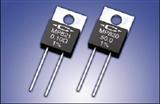
MP825 TO-126 Style Power Package
The MP825 and MP850 Kool-Pak
®
Power Film Resistors are constructed with Caddock's
Micronox®
resistance film fired onto a flat ceramic substrate. The ceramic substrate is
bonded to a copper heat sink which becomes the metal mounting surface. This
assembly is molded with the copper heat sink flush with the back surface of the part. The
terminal attachment and resistance element geometry are configured to provide
outstanding non-inductive performance.
MP825 and MP850 Power Film Resistors
Include an Integral Metal Mounting Surface
for Highly Efficient Thermal Transfer
Certain products shown in this catalog are covered by one or more patents, there are also patents pending.
MP800 Series Kool-Pak
®
Power Film Resistors
TO-220 Style and TO-126 Style - Non-Inductive Designs
• 50 Watts at +25°C Case Temperature derated to zero at +150°C.
• Copper Heat Sink Integral in the Molded Package.
• Resistance Range of 0.20 ohm to 10.0 K.
• Resistor element is electrically isolated from the mounting surface.
• Non-inductive Design.
MP820 and MP821 TO-220 Style Power Package
with Metal Mounting Tab
Use your thermal design experience with power semiconductors in TO-220 and
TO-126 style power packages to help you get the most out of this unique family of
power resistors. The thermal design issues are the same where power handling
capability is based on the case temperature which is maintained in your design.
MP850 - 50.0 - 1%
Model Number:
Resistor Value:
Tolerance
The MP820 and MP821 Kool-Tab
®
Power Film Resistors are constructed with Caddock's
Micronox®
resistance film fired onto a flat ceramic substrate which is thermally bonded to
the copper heat sink tab. The resistor body is then molded with a high temperature
molding compound to finish the metal tab TO-220 package. The lead wire attachment
and resistance element geometry are configured to provide outstanding non-inductive
performance.
For custom resistance values and tolerances contact applications engineering
MP825 Standard Resistance Values:
0.020 Ω 5%
0.025 Ω 5%
0.030 Ω 5%
0.033 Ω 5%
0.040 Ω 5%
0.050 Ω
0.075 Ω
0.10 Ω
0.15 Ω
0.20 Ω
0.25 Ω
Tolerance MP825: ±1% standard (except as noted), (0.5%, 2%,
5%,10%, and 20% are available for most resistance values).
0.30 Ω
0.33 Ω
0.40 Ω
0.50 Ω
0.75 Ω
1.00 Ω
1.50 Ω
2.00 Ω
2.50 Ω
3.00 Ω
3.30 Ω
4.00 Ω
5.00 Ω
7.50 Ω
8.00 Ω
10.0 Ω
12.0 Ω
15.0 Ω
20.0 Ω
25.0 Ω
27.0 Ω
30.0 Ω
33.0 Ω
40.0 Ω
47.0 Ω
50.0 Ω
56.0 Ω
75.0 Ω
100 Ω
120 Ω
150 Ω
200 Ω
250 Ω
300 Ω
330 Ω
400 Ω
470 Ω
500 Ω
560 Ω
750 Ω
1.00 K
1.50 K
2.00 K
2.50 K
3.00 K
3.30 K
4.00 K
5.00 K
7.50 K
10.0 K
MP850 Standard Resistance Values:
0.20 Ω
0.25 Ω
0.30 Ω
0.33 Ω
0.40 Ω
0.50 Ω
0.75 Ω
1.00 Ω
1.50 Ω
2.00 Ω
2.50 Ω
3.00 Ω
3.30 Ω
4.00 Ω
5.00 Ω
7.50 Ω
8.00 Ω
10.0 Ω
12.0 Ω
15.0 Ω
20.0 Ω
25.0 Ω
27.0 Ω
30.0 Ω
33.0 Ω
40.0 Ω
47.0 Ω
50.0 Ω
56.0 Ω
75.0 Ω
100 Ω
120 Ω
150 Ω
200 Ω
250 Ω
300 Ω
330 Ω
400 Ω
470 Ω
500 Ω
560 Ω
750 Ω
1.00 K
1.50 K
2.00 K
Tolerance MP850: ±1% standard, (0.5%, 2%, 5%,10%, and 20%
are available for most resistance values).
2.50 K
3.00 K
3.30 K
4.00 K
5.00 K
7.50 K
10.0 K
• 25 Watts at +25°C Case Temperature derated to zero at +150°C.
• Copper Heat Sink Integral in the Molded Package.
• Resistance Range of 0.020 ohm to 10.0 K.
• Resistor element is electrically isolated from the mounting surface.
• Non-inductive Design.
Construction of MP825 and MP850:
Ordering Information:
Construction of MP820 and MP821:
MP850 TO-220 Style Power Package
MP821 Standard Resistance Values:
0.020 Ω
0.025 Ω
0.030 Ω
0.033 Ω
0.040 Ω
Tolerance MP821: ±1% Standard (0.5%, 2%, 5%, 10%, and 20%
are available for most resistance values).
0.050 Ω
0.075 Ω
0.10 Ω
0.15 Ω
0.20 Ω
0.25 Ω
0.30 Ω
0.33 Ω
0.40 Ω
0.50 Ω
0.75 Ω
1.00 Ω
1.50 Ω
2.00 Ω
2.50 Ω
3.00 Ω
3.30 Ω
4.00 Ω
5.00 Ω
7.50 Ω
8.00 Ω
MP820 Standard Resistance Values:
10.0 Ω
12.0 Ω
15.0 Ω
20.0 Ω
25.0 Ω
27.0 Ω
Tolerance MP820: ±1% Standard (0.5%, 2%, 5%, 10%, and 20%
are available for most resistance values).
30.0 Ω
33.0 Ω
40.0 Ω
47.0 Ω
50.0 Ω
56.0 Ω
75.0 Ω
100 Ω
120 Ω
150 Ω
200 Ω
250 Ω
300 Ω
330 Ω
400 Ω
470 Ω
500 Ω
560 Ω
750 Ω
1.00 K
1.50 K
2.00 K
2.50 K
3.00 K
3.30 K
4.00 K
5.00 K
7.50 K
10.0 K
Packaging: MP800 Series Resistors are packaged in plastic shipping tubes,
50 pieces per tube when the order quantity permits.
Page 1 of 2
28_IL103.1004Sales and Corporate Office
1717 Chicago Avenue
Riverside, California 92507-2364
Phone: (951) 788-1700
Fax: (951) 369-1151
Applications Engineering
17271 North Umpqua Hwy.
Roseburg, Oregon 97470-9422
Phone: (541) 496-0700
Fax: (541) 496-0408
e-mail: • web: www.caddock.com
For Caddock Distributors listed by country see caddock.com/contact/dist.html
© 2004 Caddock Electronics, Inc.
CAD K DOC
DIMENSIONS IN INCHES AND (MILLIMETERS)
.640 ±.010
(16.26 ±.26)
.030 ±.004
(.76 ± .10)
.025 ± .004
(.64 ±.10)
.200 ±.010
(5.08 ±.26)
.500 ±.050
(12.70 ±1.27)
.130 ±.030
(3.30 ±.76)
.125 ±.010
(3.18 ±.26)
.410 ±.010
(10.41 ±.26)
MP850
10.0
1%
.125 ±.010
(3.18 ±.26)
.125 ±.004
(3.18 ±.10) DIA.
CL
.053 ± .007
(1.35 ± .18)
.070 ±.010
(1.78 ±.26)
Figure 2
TO-126 Style
MP825
Figure 1
Metal Tab
TO-220 Style
MP820 and MP821
MP820
50.0
1%
.540 ±.040
(13.72 ±1.02)
CL
.117 ±.003
(2.97 ±.08)
.240 ±.010
(6.10 ±.26)
.400 ±.010
(10.16 ±.26)
.200 ±.010
(5.08 ±.26)
.032 ± .004 DIA.
(.81 ± .10)
.175 ±.015
(4.45 ±.38)
.052 ±.003
(1.32 ±.08)
.580 ±.010
(14.73 ±.26)
.097 ±.010
(2.46 ±.26)
.142 ±.003
(3.61 ±.08) DIA.
Figure 3
TO-220 Style
MP850
All power and associated overload ratings are derated
based upon case temperature using the derating curve.
The case temperature is measured at the center of the
metal mounting surface, with the part properly mounted
and under electrical load. Without a heat sink, when in
free air at +25°C, the MP820, MP821, and MP850 are
rated for 2.25 watts, the MP825 is rated for 1.25 watts.
The thermal design should satisfy the following equation:
Case Temperature (T
c
) + [Thermal Resistance (RθJC) x power applied (Watts)] ≤ TMAX
considering the full
operating temperature range of the application.
Mounting Note: Mount on a smooth, clean and flat heat sink surface with a thermal interface material, such
as thermal grease. The entire exposed metal backface portion must be in thermal contact with the heat sink.
When screw mounting, use a compression washer which provides a mounting force of 150 to 300 pounds
(665 to 1330 N). This will provide sufficient pressure on the package over time and through large temperature
variations to maintain the maximum power dissipation capability. Mounting torque to avoid package damage
is 8 in-lbs (0.90 N-m). If a spring clip is used, a clip force of 8 to 30 pounds (35 to 130 N) is recommended to
be applied to the center of the package. The clip should be round or smooth in the contact area to avoid
concentrating the load on a small point of the plastic body of the package. Another mounting option is to use
a pressure bar method which can achieve a greater mounting force with a greater contact area.
For additional applications information regarding mounting and pulse handling see the Caddock
Applications Notes at caddock.com or contact Applications Engineering.
* Derating Using Case Temperature (TC):
Derating Curve
MP821
MP820
Model
No. Comments
Integral Metal Mounting Surface
in Molded Package
MP850
Integral Metal Mounting Surface
in Molded Package
MP825
Metal Mounting Tab
TO-220 Style Metal Mounting Tab
TO-220 Style
Package
TO-220 Style
TO-126 Style
0.020 Ω 9.99 Ω
10.0 Ω 10.0 K
Min. Max.
Resistance
0.20 Ω 10.0 K
0.020 Ω 10.0 K
20 Watts*
20 Watts*
Power
Rating
50 Watts*
25 Watts*
Max.
Voltage
Power
Limited
300
300
300
Thermal Resistance
RθJC
Film (J) to Case (C)
7.50°C/Watt
5.00°C/Watt
2.50°C/Watt
7.50°C/Watt
175°C
Figure 1
Figure 1
Dimensions
Figure 3
Figure 2
Max. Temp.
T MAX
175°C
150°C
150°C
+
.030 ±.004
(.76 ± .10)
.023 ± .004
(.58 ±.10)
.200 ±.010
(5.08 ±.26)
.450 ±.050
(11.43 ±1.27)
.115 ±.010
(2.92 ±.26)
MP825
0.10 Ω
1%
.110 ±.010
(2.79 ±.26)
.053 ± .007
(1.35 ± .18)
.058 ±.007
(1.47 ±.18)
.320 ±.010
(8.12 ±.26)
.094 ±.004
(2.39 ±.10) DIA.
CL
.440 ±.010
(11.18 ±.26)
.080 ±.020
(2.03 ±.51)
Specifications:
Temperature Coefficient:
TC referenced to +25°C, ΔR taken at TMAX
5.00 ohms and above, -20 to +50 ppm/°C
0.50 ohm to 4.99 ohms, -20 to +80 ppm/°C
0.050 ohm to 0.49 ohm, 0 to +200 ppm/°C
0.020 ohm to 0.049 ohm, 0 to +300 ppm/°C
Operating Temperature: -55°C to TMAX
Inductance: 10nH typical in series when measured at a point 0.2 inches from the resistor body.
DWV: The dielectric strength rating of 1500 VrmsAC
is based upon connections made between
terminals shorted and either the metal surface the
part is mounted to or a metal clip in contact with the
top surface of the part.
Insulation Resistance: 10,000 Megohms, min.
The resistor element is electrically isolated from
the mounting surface.
Load Stability: 2,000 hours at rated power.
ΔR ±(1.0 percent + 0.001 ohm) max. Power rating
dependent upon case temperature. See derating
curve.
Momentary Overload:
MP820, MP821, MP850: 2 times rated power with
applied voltage not to exceed 1.5 times maximum
continuous operating voltage for 5 seconds.
ΔR ±(0.3 percent + 0.001 ohm) max.
MP825: 1.5 times rated power with applied
voltage not to exceed 1.5 times maximum
continuous operating voltage for 5 seconds.
ΔR ±(0.3 percent + 0.001 ohm) max.
Moisture Resistance: Mil-Std-202, Method 106.
ΔR ±(0.5 percent + 0.001 ohm) max.
Thermal Shock: Mil-Std-202, Method 107, Cond. F.
ΔR ±(0.3 percent + 0.001 ohm) max.
Shock: 100G, Mil-Std-202, Method 213, Cond. I.
ΔR ±(0.2 percent + 0.001 ohm) max.
Vibration, High Frequency: Mil-Std-202, Method
204, Cond. D. ΔR ±(0.2 percent + 0.001 ohm)
max.
Terminal Strength: Mil-Std-202, Method 211,
Cond. A (Pull Test) 5 lbs. ΔR ±(0.2 percent
+ 0.001 ohm) max.
Terminal Material: Solderable
Measurement Note: For these specifications,
resistance measurement shall be made at a point
0.2 inch (5.08 mm) from the resistor body.
100 175
0
20
40
100
POWER RATING, %
80
60
150
A
B
25
A - MP825 / MP850 Max. Temperature, TMax = 150°C
B - MP820 / MP821 Max. Temperature, TMax = 175°C
CASE TEMPERATURE, °C
Page 2 of 2
28_IL103.1004